Section IX - Dismantling and Disassembly
1. General
a. The procedure outlined in this section covers dismantling of the engine into its major component parts, or subassemblies, and cleaning of these items.
b. For complete disassembling and reconditioning of the engine a number of special tools are necessary.
c. As parts or sub-assemblies are removed from the engine, they should be placed on a portable rack preparatory to being cleaned. Small boxes, tins or other receptacles should be provided in which bolts nuts, washers and other small parts can be placed as they are removed.
d. As each part or sub-assembly is removed from the engine, it should be inspected carefully before cleaning to note any unusual conditions such as sludge deposits or the collection of metallic chips. Samples of the sludge or chips, if present, should be retained for later analysis. In addition, during the various stages of dismantling, close observation must be made of all parts or components for signs of scoring or burning due to undue friction, as it often happens that many valuable indications of defects can be obtained when the oil or the loosened surface of metal is present to indicate them, rather than after all parts have been washed and laid out for examination. The sub-assemblies should be checked for the freedom of movement of all gears, shafts or bearings. After the preliminary inspection all components and sub-assemblies should be thoroughly cleaned.
e. The threads on the front end of the crankshaft should, whenever possible, be covered with a suitable thread protecting cap.
2. Dismantling Engine Into Sub-Assemblies
A. Installation on Assembly Stand
(1) After the engine has been removed from the packing box or airplane (refer to Section III), it should be attached to the Engine Assembly Stand (Tool No. FA-21) with at least four 5/16" bolts.
(2) Lock the tilting mounting plate in a vertical position. Lower the engine onto the stand allowing the carburetor side of the rear section to pass through the open portion of the mounting plate. A lifting hoist with a minimum capacity of 1/2 ton should be used. Secure the engine to the mounting plate with bolts inserted from the rear side of the plate through the engine mounting lugs on the induction housing. Install a plain washer between each mount bolt nut and the front face of the mating engine mount lug to prevent the nut from damaging the front face of the lug.
(3) Before proceeding to dismantle the engine into its various sub- assemblies it is advisable to wash the exterior of the engine thoroughly with unleaded gasoline, cleaning spirits, or cleaning compounds.
|
Note |
|
B. Removal of Ignition Wires
(1) Disconnect the ignition wires from the spark plugs. Be sure the lock is released before pulling terminal.
(2) If cylinder air deflectors are installed, remove ignition wires from cylinder head baffles, by removing grommets and pulling wires and terminals through the baffles.
(3) Disconnect and remove ignition cable clips, brackets and tube from engine.
(4) Disconnect and remove magneto blocks (with ignition cables attached) from the magnetos, exercising care not to allow the magneto blocks to strike the engine and be damaged while they are being removed.
C. Spark Plugs
(1) Remove the spark plugs.
D. Removing Cylinder Head and Inter-Cylinder Air Deflectors
(1) Before removing the inter-cylinder and cylinder head air-deflectors, mark or stamp in some suitable manner. These markings will be used to identify and determine the re-installation positions of the air deflectors after the engine is overhauled.
(2) Disconnect air deflectors from cylinders and cylinder heads.
E. Draining Oil Sumps
(1) Remove the two nuts that hold the flanged tube to the bottom of the oil sump.
(2) Loosen hose clamps on hose that connects flanged tube.
(3) Move the flanged tube away from the mounting face on the sump. This will allow the oil to drain from the sumps.
F. Removal of Accessories
(1) Magnetos
(a) Remove clevis pin and locknut from the eye on the end of each magneto lever.
(b) Remove magneto control rod assembly.
(c) Install a turning bar, FA-182, or Timing Disc, FA-16-2, on the crankshaft.
(d) Turn crankshaft until one of the two screws on the front side of a magneto coupling is on top.
(e) Remove screw.
(f) Repeat procedures (d) and (e) for removing the remaining screws on the couplings.
(g) Remove the magneto retaining bolts and washers.
(h) Remove magnetos.
Caution
Unless magneto brackets are damaged and must be replaced, they must never be loosened or removed as the magneto face of the bracket is machined on a holding fixture to ensure proper alignment of magneto coupling drive and magneto shaft.
G. Removal of Gearcase and Attaching Parts
(1) Starter
(a) Remove nuts and washers which hold the starter to the adapter, and carefully remove starter.
(b) Remove nuts and washers which hold the-adapter to its mounting flange and remove adapter.
(c) To remove the starter jaw assembly, loosen the set screw in center of shaft. This screw tightens an eccentric washer which locks behind the mating splines of the starter clutch. The starter jaw can be withdrawn when the set screw is loosened sufficiently to allow the washer to center in the opening below the splines.
(2) Magneto Drives
Remove retaining nuts, lockwashers and drives, tapping drive with fiber or rubber mallet if necessary.
(3) Remove oil sump tube from oil pump by loosening hose clamp if pump is equipped with fuel pump drive, or remove nuts and lockwashers from flanged tube on pump if there is no fuel pump drive on pump.
(4) Unscrew and remove oil inlet fitting bolt, and fitting directly underneath oil pressure regulating valve.
(5) Remove oil pump retaining nuts and lockwashers.
|
Note |
|
(6) Remove gearcase retaining nuts and lockwashers and pull off gearcase.
|
Note |
|
(7) Drive out oil pump tram gearcase by tapping on the slotted drive shaft with a fiber or rubber mallet.
H. Removal of Breather Elbow and Tachometer Drive Housing
(1) Remove the two nuts and lockwashers from breather elbow and pull off breather elbow.
|
Note |
|
I. Removing Idler Gear
(1) While crankshaft extension shaft is still in place remove the three idler shaft gear retaining screws.
(2) Remove gear from idler shaft flange
(3) Pull out crankshaft extension.
J. Removing Oil Sump
(1) Turn engine in flat position with crankshaft pointing up.
(2) Remove screw from front of oil sump at supporting link.
(3) Remove the two nuts and lockwashers at rear of oil sump.
(4) Pull sump off studs.
K. Removal of Cylinders and Pistons
(1) Remove all rocker box covers which are retained by spring clips.
(2) Remove all of the intake pipe eta1ning nuts and lockwashers.
(3) Remove intake p1pes, spr1ngs, glands and pack1ngs.
(4) Using special cylinder base palnut wrench, No. FA-11238, remove the palnuts from the cylinder hold-down studs. See Figure 6.
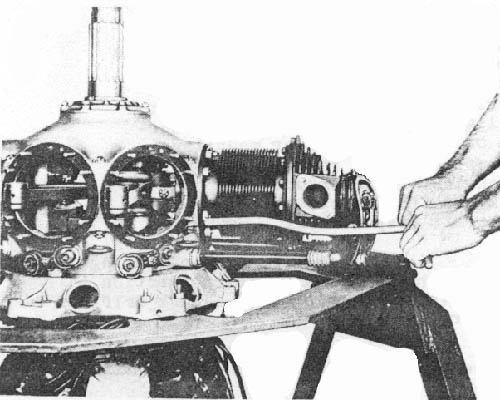
Figure 6 - Removing Cylinder Base Hold Down Nuts and Palnuts
(5) In removing the cylinders, the No.1, or Master rod cylinder, is the last one to be removed.
(6) Before removing the cylinder from the crankcase, bring the piston in that cylinder to the top of its stroke. This can be done by rotating the crankshaft until the piston can be observed through the spark plug hole to be at the top of its stroke.
(7) Turn the crankshaft until the No.2 piston is at the top of its stroke.
(8) Remove cylinder hold-down nuts with cylinder base nut wrench No. FA-33-A, see figure 6. Jiggle cylinder loose and remove push rod tubes and push rod.
|
Note |
|
(9) Turn the crankshaft until No. 3 piston is at the top of its stroke, remove cylinder hold-down nuts and pull off the cylinder as instructed above.
(10) Continue on around the engine, going through the same steps as above until No. 1, the master rod cylinder, is removed last.
(11) After removal the cylinders should be set down on wood or some other soft surface in order not to distort or burr the ends of the barrels.
(12) Pistons are removed by first pushing out the piston pins.
|
Note |
|
L. Removal of Carburetor Air Heat Control Valve and Carburetor
(1) Carburetor Air Heat Control Valve
(a) Loosen and remove the screws and washers that attach the carburetor air heat control value to the carburetor.
(b) Remove the carburetor air heat control valve.
(2) Carburetor
(a) If safety wired, break and remove all safety wire on studs that secure carburetor to induction housing.
(b) Loosen and remove retaining nuts and washers that secure carburetor to induction housing.
(c) Remove carburetor.
M. Removal of Thrust Nut, Thrust Cover, Oil Slinger, Crankcase Front Section and Bearing Spacer
|
Note |
|
(1) Thrust Nut
(a) Using crankshaft turning bar No. FA-182 to hold crankshaft, loosen thrust nut with wrench FA-183-1. See figure 7 for method of removal.
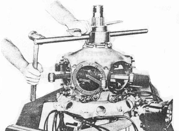
Figure 7 Removing Crankshaft Thrust Nut
(b) Remove thrust nut.
(2) Thrust Cover And Oil Slingers
(a) Remove the thrust cover retaining nuts and washers.
(b) Remove thrust cover and oil slinger.
(3) Crankcase Front Section and Bearing Spacer
(a) Remove cotter pins and retaining nuts and washers from the six crankcase bolts and bottom stud.
(b) Drive back the six crankcase bolts, that are between cylinders but do not try to drive back the protruding end of stud between cylinders No. 4 and 5. This stud will act as a guide when the crankcase front section is being pulled from the crankshaft.
(c) Attach puller No. FA-197-A to the thrust cover studs with retaining nuts. Install spacer FA-197-B on the end of the crankshaft to provide a bearing seat for puller screw. See Figure 8.
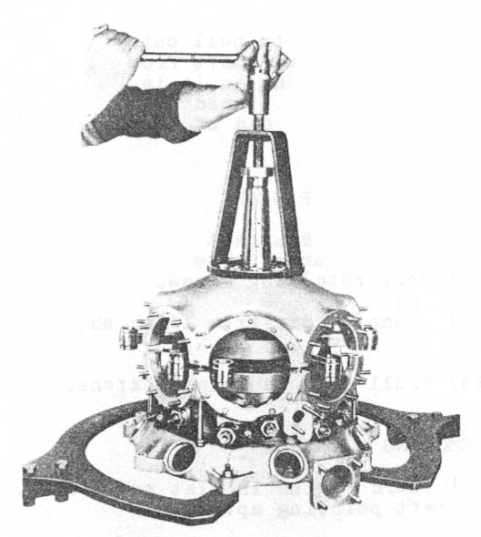
Figure 8 - Removing Crankcase Front Section
(d) Turn puller screw until crankcase front section is free of guiding stud and bolts. Remove crankcase front section
Note
While pulling crankcase front section care should be exercised that it comes up straight and does not bind on the guiding stud. If binding should be experienced, with a raw-hide mallet tap lightly the crankcase front section on the thrust cover mounting pad surface which faces the front of the engine. This should free the crankcase front section from binding and permit easy removal.
(e) If the front main bearing comes off with the crankcase front section it can be removed by tapping with a soft drift on the outer race only.
(f) Remove bearing spacer if it has not been pulled off the crankshaft with the crankcase front section.
(g) If the front main bearing remains on the crankshaft place the bearing puller No. FA-213-A, with the horseshoe shaped base straddling the front cheek and resting against the outer race of the bearing. See Figure 9.
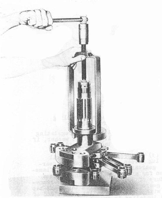
Figure 9 - Removing Crankshaft Front Main Bearing
(h) Place disc No. FA-197-B on the front end of the crankshaft to act as a bearing seat for the puller screw.
(i) Holding crankshaft in place turn screw and lightly tap bearing with a rawhide hammer until front main bearing can be removed from crankshaft
N. Removal Of Crankshaft and Master Rod Assembly From Crankcase Rear Section
|
Note |
|
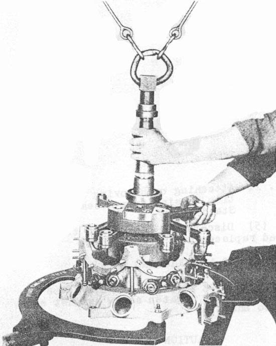
Figure 10 - Removing Crankshaft And Connecting Rod Assembly From Crankshaft Rear Section
(1) Screw on propeller hub nut down as far as possible on crankshaft.
(2) Attach a suitable hook or sling to the propeller hub nut and by means of a chain or power hoist and pull crankshaft assembly straight up.
(3) If propeller hub nut is not installed on crankshaft use a No.20 SAE propeller hub nut.
O. Removal Of Crankcase Rear Section From Induction Housing
(1) Rotate engine assembly plate so that crankcase rear section and induction housing are in a horizontal or "flight" position. Lock the plate in this position.
(2) Remove the cotter pins and retaining nuts and washers from the studs that attach the crankcase rear section to the induction housing. These retaining nuts and washers are located on the rear face of the induction housing.
(3) Tap the ends of the studs with a soft mallet. This will aid in separating the crankcase rear section from the induction housing.
(4) Remove the crankcase rear section from the induction housing.
P. Removal Of Induction Housing From Assembly Stand
(1) Loosen and remove all nuts and washers from bolts that attach induction housing to assembly stand plate. See Figure 11.
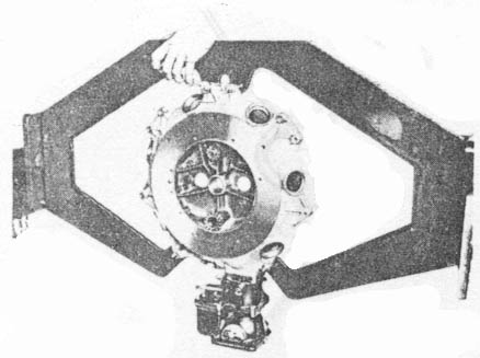
Figure 11 - Attaching Or Removing Induction Housing From Assembly Plate Stand
(2) Remove Induction housing from assembly stand plate.
3. Disassembly of Sub-Assemblies
A. Ignition Cables, Terminals, And Magneto Distributor Blocks
(1) Disconnect all cables from the magneto distributor blocks to which they are attached by means of a screw.
(2) Replace and secure the magneto distributor blocks on their magnetos.
(3) Remove all ignition cables from the ignition cable tubes.
(4) Remove rubber rings and all attaching clips from ignition cables.
(5) Discard all cables and terminals that need replacement.
B. Magneto and Coupling
(1) Using gear puller No. FA-268 as shown in figure 12 tighten screw against end of magneto shaft.
|
Caution |
|
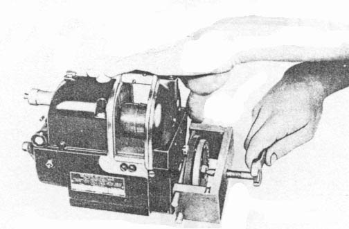
Figure 12 - Removing Magneto Coupling Assembly From Magneto.
(2) Tap end of gear puller screw lightly with a hammer, at the same time increasing the tension on the screw until coupling breaks loose of the taper seat on magneto shaft.
(3) Remove nut and coupling.
(4) Remove 4 castle nuts from magneto coupling and disassemble the component parts. The studs on the ring are riveted and cannot be removed.
C. Magneto Drive
(1) Remove cotter pin, nut and washer from the end of the drive shaft.
(2) Remove gear and Woodruff key from shaft.
(3) Push the drive shaft out of the magneto drive housing.
(4) Push out bearing, spacer and oil slinger using a drift if necessary.
|
Note |
|
D. Gearcase
(1) Remove acorn nut, oil screen plug and oil screen from gearcase on left side.
(2) Remove oil pressure regulating valve plug, spring, ball and flat washer, if any, from gearcase on the right side.
(3) In order to remove the oil screen plug screen assembly from the gearcase the gearcase must be heated in a flameless oven for a period of 30 minutes at a temperature of 300° Fahrenheit. After removing the gearcase assembly from the oven, tap lightly with a raw hide mallet on the end of the stud installed in the plug assembly.
(4) With wrench FA-99 unscrew pressure regulating valve bushing.
|
Note |
|
E. Oil Pump
(1) Remove inlet and outlet connections.
(2) Remove four pump body retaining screws from the front of oil pump.
(3) Secure the pump in a vise by clamping the vise jaws on the slotted end of the pump drive shaft across the slot.
(4) Remove the rear pump body.
(5) Remove fuel pump drive shaft and disassemble the two rings, scavenger idle gear and Woodruff key from shaft.
(6) Remove ring from oil pump drive shaft.
(7) Remove scavenger pump drive gear and woodruff key from pump drive shaft.
(8) Remove oil pump spacer.
(9) Remove pressure pump idler gear.
|
Caution |
|
(10) Remove pressure pump drive gear and Woodruff key from pressure pump drive shaft
(11) Remove pressure pump drive shaft from housing.
(12) Using tool No. FA-245, remove oil pump drive shaft oil seal from oil pump rear body.
(a) Install plate No. FA-245-A with smaller pilot against oil seal.
(b) Secure plate with two nuts to fuel pump mounting face.
(c) Drill four holes into the seal through the inner four pilot holes in plate No. FA-245-A using a #40 (.098 dia.) drill. Drill holes into seal not more than 1/8" deep.
Caution
Do not drill through outer four holes of the plate. This would damage the pump housing.
(d) Install four #6 x 5/8 long Round Head Self-Tapping, screws through the plate and into the seal.
(e) Install pulling bracket No. FA-245-B over the two remaining studs on mounting face.
(f) Install washer and pulling screw through pulling bracket No. FA-245-B into plate No. FA-245-A.
(g) Remove the two retaining nuts from the plate.
Caution
Do not try to remove seal with plate secured to studs because the studs would be pulled and pump housing damaged.
(f) Remove seal by turning screw.
Note
After removing seal do not discard the self tapping screws as they are a part of Tool No. FA-245.
F. Oil Sump
(1) Remove nuts and lockwashers from bottom of sump.
(2) Remove oil sump bottom cover, screen and gaskets.
G. Cylinders
|
Caution |
|
(1) Remove cotter pins, nuts and washers from rocker arm shafts.
(2) Remove rocker-arm shafts.
(3) Remove lubrication fittings from shafts.
(4) Remove rocker arms and washers.
(a) Using a 1/4" diameter soft drift, drive out rocker arm bearing. Insert drift through one side of the rocker arm and tap against inner race of bearing on other side of the rocker arm. The bearing should be driven out uniformly by tapping all around the bearing inner race.
(b) Remove bearing spacer.
(c) Using a soft drift tap out second bearing from rocker arm.
(5) Do not remove the rocker arm roller.
(6) Removing valves, springs, washers and retainers:
(a) Place cylinder on valve spring assembling stand No. FA-188 and use Valve Spring Depressing Tool No. FA-104 from tool kit.
(b) Turn cylinder over and remove valves.
Note
When turning cylinder over hold both valves in the guides in order to prevent them from sliding out and hitting against the cylinder walls.
(7) Remove exhaust flange shipping baffles if any have been installed on the cylinders.
H. Pistons and Pins
|
Note |
|
(1) Do not remove piston pin plugs from pin unless they are loose and require replacement.
|
Note |
|
(2) Using piston ring spreader No. FA-67, remove the rings from piston.
I. Carburetor Heat Control Valves
Unless damaged it is unnecessary to disassemble the carburetor heat control valve.
J. Thrust Cover
Do not attempt to remove the thrust ring from the thrust cover. Ring is permanently attached to cover and cannot be removed without damage to cover.
K. Crankcase Front Section
(1) Remove thrust bearing from crankcase front section by tapping on outer race of bearing with a soft drift.
|
Caution |
|
L. Crankshaft And Master Rod Assembly
(1) Place the crankshaft in a vise with copper covered jaws, as shown in Figure 13. Clamp vise jaws securely against front crankshaft cheeks.
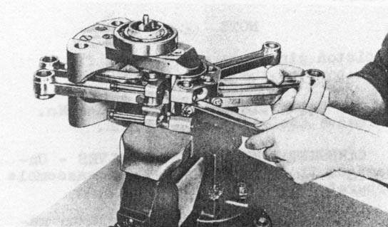
Figure 13 - Method of Clamping Crankshaft Assembly in Bench Vise For Disassembly.
(2) Remove cotter pin and retaining nut from one master rod bolt.
(3) Remove bolt from master rod and replace nut on master rod bolt, to avoid necessity of selecting nuts at assembly.
(4) Continue with other three bolts as above until they are all removed from master rod.
(5) Remove the two master rod sections from the crankshaft.
(6) Remove long 1/8" diameter cotter pin from rear cheek of crankshaft.
(7) Reset crankshaft in vise and clamp rear cheek securely as shown in Figure 14.
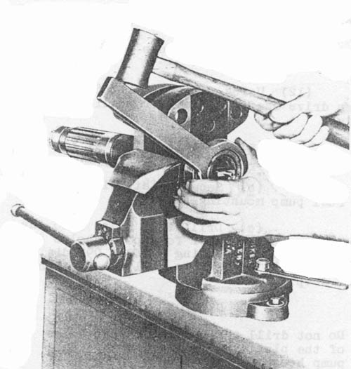
Figure 14 - Method of Clamping Crankshaft In Bench Vise for Removal of Rear Main Bearing Retaining Nut.
(8) Remove rear bearing retaining nut lock ring.
(9) Using wrench No. FA-71-1 and a hammer, remove rear bearing retaining nut as shown in Figure 14.
(10) Reset crankshaft in vise.
(11) Place horseshoe shaped base of tool No. FA-213-A to straddle rear cheek of crankshaft and rest against the inner race of rear main bearing.
(12) Place long spacer No. FA-213-B on the rear end of the crankshaft to act as a bearing seat for puller screw.
(13) Use same procedure to remove rear main bearing as was used with this tool to pull front main bearing. See figure 15.
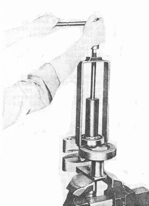
Figure 15 - Method of Removing Rear Main Bearing From Crankshaft.
(14) Reset crankshaft in vise as shown in Figure 12 and drive coupling pin out, using a soft drift.
(15) Remove coupling.
(16) Using Tool No. FA-194 remove crankpin plug. See Figure 16.
|
Note |
|
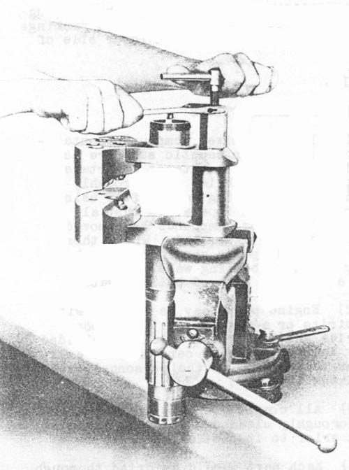
Figure 16 - Method of Removing Crankshaft Crankpin Plug From Crankshaft.
M. Master Rod and Link Rods
(1) Remove bearing shells from the master rod by tapping them lightly with a soft mallet if necessary.
(2) Remove nuts and bolts from all link rods.
(3) Prior to driving out the wrist pins place a small steel wedge between the inner surface or the master rod and the bottom surface of the flanges of the link rod "I" section. This precaution will eliminate any possibility of the bushings being moved and loosened when the wrist pin is being driven out. This precaution is important as any movement of the wrist pin bushing will partially close the oil supply hole from the master rod bearing, as well as causing excessive side clearance in the link rod.
(4) With wedge in place drive out wrist pin.
(5) Using same procedure as outlined above remove all remaining link rods.
N. Crankcase Rear Section
(1) Remove cam ring retaining snap ring. This can be done by pressing with a screw driver against the tongue of the snap ring, which protrudes into the rear main bearing sleeve. With another screw driver disengage snap ring from groove.
(2) Remove cam ring and bushing from rear main bearing sleeve.
|
Note |
|
(3) Remove cotter pins and retaining nuts from the crab studs.
(4) Remove crabs.
|
Note |
|
(5) Remove cam follower guides with cam followers.
O. Induction Housing
(1) Remove primer connection if one has been installed on the engine.
(2) Removing cam drive idler shaft.
(a) Remove the bolt and nut from the hub of the gear flange.
(b) Pullout oil pump drive coupling
(c) Remove gear flange using puller FA-191. A disc or flanged plug must be placed over the end of the shaft for the puller screw to push against. The diameter of the disc or flange on the plug must be smaller than the hole in the flange.
(d) Remove the Woodruff key from the idler shaft.
(e) Pullout idler shaft from the front side of the induction housing.
(3) Removing Tachometer Drive Shaft
(a) Pry end of spring from hole in shaft and pull off spring, washer and packing.
(b) Close the slotted end of the tapered retaining pin in hub of gear.
(c) Pull gear off shaft.
(d) Pull shaft out from rear side of induction housing.
P. Cam Follower Guide
Remove the packing nuts, plain washers, spring washers and packings from the six guides removed from lower side of the crankcase.
4. Cleaning
A. General Instructions
(1) If water mixed compounds containing any form of soap or caustic soda are used for cleaning, it is of the utmost importance that all parts or assemblies be thoroughly cleaned with clear boiling water after using such compounds. It is imperative that all traces of the cleaning compounds be removed before the parts are assembled. Where these compounds are used, parts should be scrubbed thoroughly in clear boiling water and then rinsed in a separate bath of boiling water.
(2) Engine parts may be cleaned with mineral spirits or a mixture of 50% carbon tetrachloride and 50% benzol or clear unleaded gasoline. However, extreme care must be exercised to prevent injury to the personnel when handling these mixtures.
(3) All component parts of the engine must be thoroughly cleaned of all oil, grease, and carbon prior to inspection.
(4) Each part should be dried thoroughly with compressed air and placed on the rack. If the parts are to remain on the racks for any length of time they should be sprayed or slushed with engine oil or suitable slushing compound to prevent corrosion.
B. Cleaning Procedure
(1) General - After the external surfaces of the parts are cleaned, a special effort should be made to insure that all internal passages of the engine are thoroughly cleaned and blown out with compressed air. Particular attention should be paid to the oil passages of the crankshaft, induction housing, oil pump and oil sumps.
(2) Pistons - Scrape carbon from all ring grooves using every precaution not to cut or damage the lands. Hard carbon may be removed from the top and bottom of the piston head by careful scraping or by sandblasting with #120 sand propelled by not over 30 pounds air pressure. If sandblasting is used it should only be done after the piston pin holes have been plugged and the O.D. of the piston covered from the bottom of the skirt to the top of the head. The glazed surfaces present on the piston skirt will not be removed, except score marks will be removed by light stoning or kerosene soaked crocus cloth. Clean the bore of the piston pin holes with kerosene soaked crocus cloth. Carbon lodged in the oil holes should be removed by cleaning with an undersized drill if required. Final cleaning of the pistons may require polishing of the head with kerosene soaked crocus cloth.
(3) Cylinders - Removal of the hard carbon from the combustion chamber and enamel from the outside of the cylinders before repainting may be done by sandblasting. Observe instructions for sandblasting as given for piston heads.
(a) Prepare cylinders for sandblasting or scraping of the carbon from the combustion chamber by installing a suitable cylinder wall protector sleeve in the cylinder. If sandblasting is to be used, install rubber plugs in the valve guide from the inside. The threaded holes in the spark plug bushings should be protected with rubber plugs or with dummy or discarded plugs. It is permissible to sandblast the valve seats. This is often desirable, as it cuts the carbon or glaze that is apt to form on the seats, particularly the exhaust, and facilitates reconditioning.
|
Caution |
|
(4) Valves - Any hard carbon remaining on the heads of the valves after removal from the cleaning solution may be removed with a fine wire brush.
(5) Master Rod Bearings - To clean the master rod bearing wipe the bearing with a clean cloth saturated with unleaded gasoline or carbon tetrachloride. Do not attempt to clean used bearings by any other means such as polishing, burnishing or subjecting them to the action of any cleaning solution other than unleaded gasoline or carbon tetrachloride.