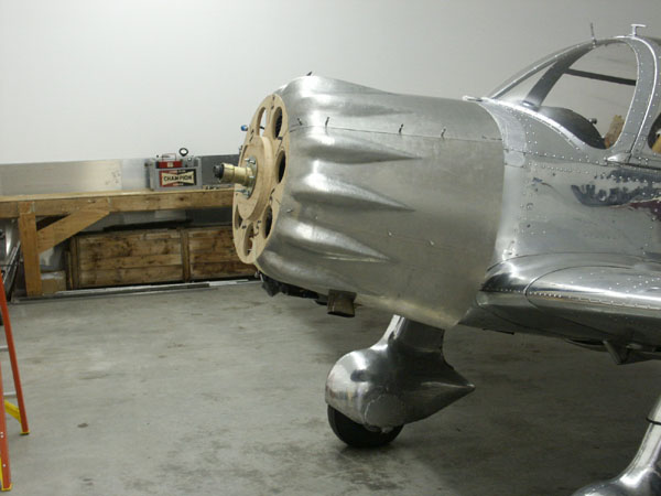
Fitup
Once each piece is fitted up, it is then trimmed and carefully fitted together with the adjacent panels using an overlapping seam. The seam area is then drilled for rivets. The left side of the cowling all together is shown in this photo. The spiky things sticking out the side are temporary sheet metal assembly fasteners called clecos. They're used to take the place of tension rivets while assembling, and can be installed or removed by squeezing a spring loaded plunger using a special set of pliers. Clecos are indispensable for sheet metal work.
In the previous photo, the lower rear of the cowling appears a bit large on the bottom. After a visit, Ron agreed to bring in the bottom edge by adjusting the fit of the side panels.
The bottom cylinders have a unique rocker box cover on the bottom two boxes, which forms the gravity-drain oil sump for the rocker boxes. These sump-covers require a larger than normal bump, one that is rather square. Ron cut the bump sides out of a practice panel, then welded it into a single large square bump.
This piece will in turn be cut in half and then welded to the bottom of the side panels. The cowling bottom seam will run up the middle of this big bump.
July 3rd, 2004 - Planishing
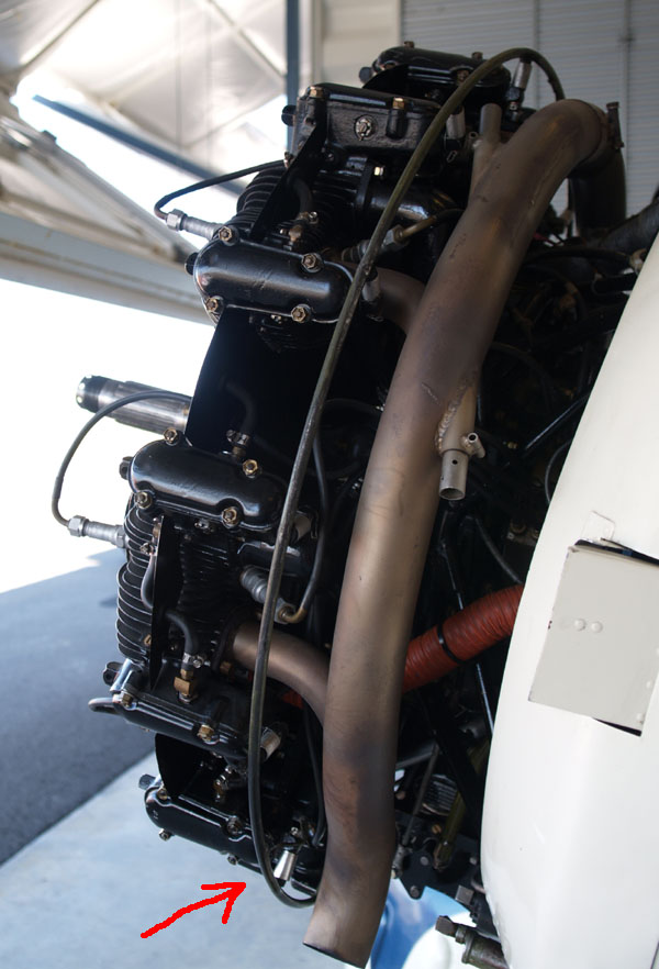
Ron has been thinking about the cowling mount arrangement around the engine. The top of the cowling is hinged with piano hinge, and is mounted on a channel that runs along the top of the cowling from the top of the engine to the firewall. Unfortunately that will only locate the cowling on the top, but it won't be enough to prevent the cowling from moving around on the engine and rubbing through. To solve this problem, the proposed solution is to build a steel tubing ring around the engine, and have a U channel riveted into the inside of the cowling to fit over the ring. Here's a picture of a similar system from a Cessna Airmaster:
This will positively locate the cowling fore/aft as well as spacing around the engine radially. Finalizing the mounting system is blocking most other progress except for planishing, which is the process of smoothing out the slightly rumpled look left from forming and hammering out the bumps. If you're painting a surface then you can hide a lot of imperfections with a little bit of bondo and some paint, but if you're polishing then the surface must be perfectly smooth. This is achieved in several passes.
The first pass is to use plastic dies in the power hammer, with low-power hits, to smooth out the biggest low and high spots. This is effective but it is just the first pass, and it will leave the metal relatively smooth but visibly rumpled and quite obviously rumpled to the touch. The next step is to do a little bit of sanding with 220 grit sand paper, to take off the top few thousands of the aluminum and really make the low spots visible. The sandpaper leaves scratches but it makes the low spots obvious and dramatically smooths out the metal.
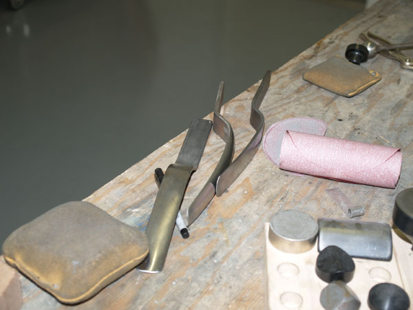
Post sanding, the low spots become visible and each must be raised by hand. The method is to use a slapper, pictured below, to hit the top of the part, and a backing domed die below the area to be raised. The trick is to align where the die is with where the slapper hits. When they are aligned there's a distinct ding'ing noise and the low spot is raised in the hit area. By carefully moving the die and slapper hits around in the low area, it is raised up. The area being hit can usually be seen with a bright polished "coined" area resulting from the hit.
If there's a high area, then hitting with the slapper backed by a shot bag will low the metal. Progressive refinement results in a smooth part. Needless to say this takes some touch and a lot of patience.
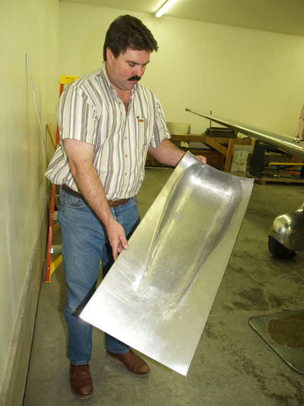
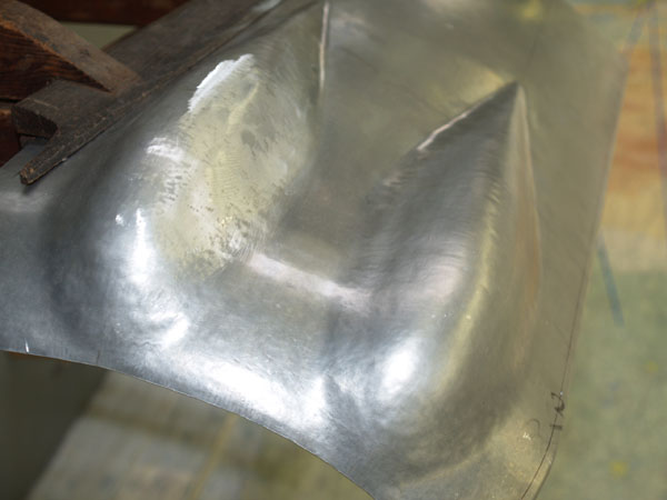
Here is a panel where planishing has just been started. The bump on the right hasn't seen any work - notice the rumply surface. If you polished this, it would be very visibly rough.
The bump on the left has been run through the power hammer with plastic planishing dies, then sanded lightly. The sanded areas are shinier, because the surface is getting smooth. The low spots show up as darker areas, and each is raised with a slapper and die. High spots are harder to see but can be fairly easily felt. The fingers are amazingly sensitive surface discriminators!
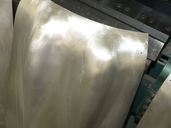
Here is a panel after much planishing and sanding. This is ready for the next steps which is progressively sanding with finer grit sandpaper up to about 1000, to remove scratches. Then the first polish pass will reveal a multitude of sins including highs/lows and more scratches. Wash, rinse, repeat.
Next: Fitup to the Airplane